
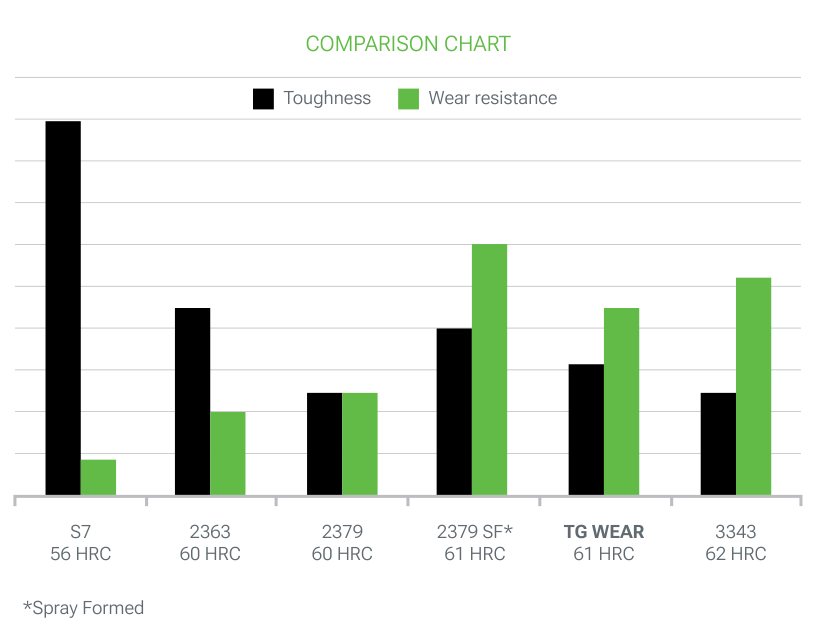
Optimized tool steel with excellent wear resistance and high toughness
TG Wear;
- is a 7.5% Cr steel produced by a process that ensures a good level of cleanliness.
- is an air hardening tool steel with an excellent combination of high wear resistance and toughness TG Wear has good dimensional stability, and good compressive strength.
- has excellent suitability for surface treatments such as gas, ionic or salt bath nitriding, as well as PVD or CVD coatings.
- is intended for applications that require higher wear resistance than D2 and toughness like A2.
Applications
TG Wear is used in cutting tools as shredder blades, shear blades, knives. TG Wear is also used for punches, blanking dies, thread rolling dies, coining dies, trim dies. TG Wear is used for gauges and various wear parts.
Main properties
- Good abrasive and adhesive wear resistance
- Very good toughness
- Good compressive strength
- Good dimensional stability
- Suitable for surface treatments
Designation
| Werkstoff Nr | ISO | China GB | JIS Japan | UK | AISI USA | Russia Gost | AFNOR | Other / Special |
|---|---|---|---|---|---|---|---|---|
| – | X110CrVMoW 7-2 | – | – | – | – | – | – | – |
Chemical composition (typical)
| C | Mn | Si | P | S | Cr | V | Mo | W |
|---|---|---|---|---|---|---|---|---|
| 1.07 | 0.32 | 1.10 | ≤ 0.030 | ≤ 0.025 | 7.50 | 2.40 | 1.55 | 1.15 |
Structure
The structure of the TG Wear is fine and homogeneous without precipitation or alignments of carbides. The TG Wear is ingot casted to guarantee fine primary carbides with a homogeneous distribution in the product.
Hardness at the time of delivery
Annealed for 260 HB max.
Physical properties
| Temperature | 20°C | 100°C | 200°C | 300°C |
|---|---|---|---|---|
| Volumic mass kg/m³ | 7830 | 7800 | 7750 | 7700 |
| Young Modulus N/mm² | 207000 | 199000 | 192000 | 187000 |
| Thermal conductivity W/m.K | 20 | 20 | 21 | 21.5 |
| Coefficient of linear expansion 10-6/K | 12 | 12.3 | 12.4 | 12.5 |
Heat treatment
Soft annealing
Temperature: 870°C, duration 1h + 1h for 25 mm thickness. slow cooling in the furnace (10 to 20°C/h). The atmosphere in the furnace must be reducing to avoid decarburization of the steel.
Stress relieving
After machining, it is recommended to perform stress relieving at 650°C for a minimum of 2 hours, followed by slow cooling in the furnace to 450°C.
Austenitization
In order to avoid any risk of cracking it is recommended to preheat in 2 steps.
- 1st preheating step: temperature: 550°C time: 30 s/mm of thickness
- 2nd preheating step: temperature: 850°C time: 30 s/mm of thickness
Recommended austenitizing temperature: 1010 – 1050°C. The holding time should not be too long to avoid a risk of grain coarsening and a loss of toughness. It is recommended to keep the part at the austenitizing temperature 30 minutes per inch of thickness as soon as the temperature of the surface reach the austenitization temperature.
Temperatures over 1020°C are not recommended in order to avoid big amounts of retained austenite leading to a poor stability and the risk of cracks.
| Hardening temperature °C | Tempering temperature °C | HRC Hardness | Longitudinal size change in % |
|---|---|---|---|
| 1010 | 510 | 62 | 0.0 / +0.06% |
| 1065 | 510 | 63 | 0.0 / +0.08% |
Quenching medium
Oil at 80°C, vacuum (pressure > 6 bars), salt bath 500 – 550°C.
To ensure good toughness, treatment with oil or salt bath is preferable.
Sub zero treatment
For parts that need to have high dimensional stability and to increase wear resistance without reducing toughness, it is recommended to perform a subzero treatment at a temperature between -70°C and -190°C for 1 hour for 25 mm of thickness of the part.
The temperature range from -70°C up to -120°C (named cold treatment of steel) leads to the complete transformation of austenite into martensite and as a consequence to better stability associated with improved hardness and better wear resistance and the temperature range from -135°C down to -190°C (named cryotreatment of steel) leads also to the complete transformation of austenite and also the precipitation of ultrafine carbides improving a lot the wear resistance without modification of the toughness. This treatment is optional for common applications.
Tempering
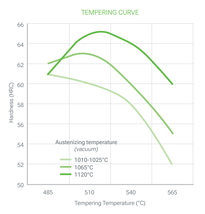
To ensure a minimum residual austenite rate as well as greater tool stability, it is essential to perform a double (better triple) tempering. Each tempering is followed by a cooling under 100°C. Depending on the use of the final part the following tempering temperatures are recommended:
| Austenitizing temperature | Tempering temperature | Hardness | Properties |
|---|---|---|---|
| 1030 / 1040°C | 500°C | 58 / 60 HRC | Better toughness |
| 510°C | 59 / 61 HRC | Wear and toughness | |
| 540°C | 60 / 62 HRC | Better wear resistance |
Each tempering time must be at least equal to 1h + 1h for 25 mm of thickness of the treated part (equivalent thermal thickness).
Surface treatment
Nitriding
TG Wear can be nitrided at temperatures less than or equal to 20°C below tempering temperatures without risk of deterioration of the mechanical characteristics. The hardness of the nitride layer is around 1100 HV1 and the thickness is dependent on the nitriding process.
PVD, CVD
TG Wear is suitable for all kinds of PVD and CVD treatment as soon as the treatment temperature is 30°C lower than the last tempering temperature.
Machining
The machining parameters below are given for information only and must be adapted according to the equipment and usual machining conditions.
Turning
| Carbide tool Rough machining |
Carbide tool Finishing |
HSS tool Finishing |
|
|---|---|---|---|
| Cutting speed m/min | 100 – 150 | 140 – 200 | 10 – 15 |
| Feed mm/r | 0.2 – 0.4 | 0.1 – 0.2 | 0.1 – 0.3 |
| Depth of cut mm | 2 – 4 | 0.5 – 2 | 0.5 – 2 |
Milling: surfacing
| Milling with carbide tools Rough machining |
Milling with carbide tools ½ Finishing |
Solid tool Finishing |
|
|---|---|---|---|
| Cutting speed m/min | 100 – 120 | 160 – 180 | 80 -100 |
| Feed mm/r | 0.2 – 0.4 | 0.1 – 0.2 | 0.02 – 0.2 |
| Depth of cut mm | 2 – 4 | 0.5 – 2 |
Drilling: HSS twist drill
| Drill diameter mm | Cutting speed m/min | Feed mm/t |
|---|---|---|
| < 5 | 10 – 12 | 0.05 – 0.15 |
| 5 – 10 | 10 – 12 | 0.15 – 0.20 |
| 10 – 15 | 10 – 12 | 0.20 – 0.25 |
| 15 – 20 | 10 – 12 | 0.25 – 0.30 |
Drilling: carbide drill
| Carbide type | Indexable insert | Solid carbide | Carbide tip |
|---|---|---|---|
| Cutting speed m/min | 130 – 150 | 80 – 90 | 35 – 45 |
| Feed mm/t | 0.05 – 0.10 | 0.10 – 0.25 | 0.15 – 0.25 |
Fine grinding
General indications for grinding wheels to be used on TG Wear in the heat treated condition. Usually, rather soft vitrified aluminum oxide grinding wheels (grades G for plane grinding to K for cylindrical grinding) are used.
Particular attention will be paid to effective cooling of the surface during grinding to prevent degradation of the material surface.
Electro-discharge machining
TG Wear is also suitable for EDM machining (wire or electrode). Preferably, the machining will be carried out with a low current density and a high frequency in order to limit the thickness of the white layer as much as possible.
Then it is necessary to carry out a stress relieving at 25°C below the last tempering in order to reduce the level of residual stresses (which could lead to a risk of cracking) and to carry out a polishing to completely remove the white layer formed during the discharge machining process.
Welding
TG Wear cannot be welded.
Download the TG WEAR datasheet (PDF)
More grades: Cold Work Tool Steels. Where to buy: Service Network.

